


|
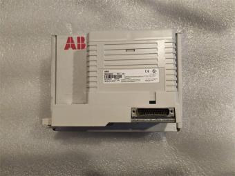
Manufacture |
GE |
|
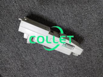
Model |
DS200TCCBG1BZZ |
| PN No. | DS200TCCBG1BZZ |
|
Catalog |
MKV |
|
Description |
Expanded Analog Card (C-core)
|
| Origin | USA |
| HS CODE |
85389091 |
| Dimension |
18*16*5 (CM) |
| Weight | 0.5 kg |
Description:
DS200TCCBG1BZZ GE MKV, Expanded Analog Card (C-core)
DS200TCCB - Common Extended Analog IO Board
The Common Extended Analog I/O Board (TCCB) provides scaling and conditioning for additional analog I/O signals read from the TBCB terminal Board mounted on the <R5> core and the TCEB board in the <P1> core. These signals include 4-20 mA/0-1 mA inputs, RTDs, generator and bus voltage inputs, and the line current inputs.
The STCA board receives the scaled and conditioned signals via the 3PL connector.
TCCB Connectors
2PL - Distributes power from the TCPS board in the <R5> core.
3PL - The Data Bus between the STCA, TCCA and TCCB boards in core <R5>.
Conditioned signals are carried on 3PL for transferring to the COREBUS.
JHH - Carries the 4-20 mA/0-1 mA input signals from the TBCB terminal board.
JII - Carries the RTD input signals from the TBCB terminal board.
JMP - Carries the potential and current transformer (PT and CT) signals from the TCEB board in the <P1> core.
JKK - Typically not used.
JTEST - Typically not used.
TCQPL - Typically not used.
The hardware document in Appendix B and the signal flow diagrams in Appendix D contain more information.
TCCB Configuration
Hardware. The hardware jumpers J1, J2, J3, J4 and J5 are used to provide the generator and bus voltage monitoring functions and the line current monitoring function in the Mark V LM. Hardware jumper J14 is used to connect the RS232 serial port to DCOM. Hardware jumpers J15 and J16 are used for testing purposes. Refer to Appendix A and the hardware jumper screen on the operator interface for information on the hardware jumper settings for this board.
Software. I/O configuration constants for the RTDs, mA inputs, the generator and bus voltage and line current settings are entered in the I/O Configuration Editor located on the HMI as described below.
TCCB 4 - 20 mA Input Circuit
The TCCB board provides the circuitry for the 420 mA and 01 mA input signals. The signals are read from the TBCB terminal board via the JHH connector. The transducer current is dropped across a burden resistor and the voltage drop is read by the TCCB board and written to the I/O Engine via the 3PL connector. Hardware jumpers on the TBCB terminal board are used to select the current range of the input signals.
TCCB RTD Circuit
The circuitry that supplies excitation to the RTDs from the TBCB terminal board is located on the TCCB board. A steady current is sent through the RTD and when the temperature changes, the resistance changes causing the voltage on the RTD to change. The TCCB board measures, scales, and conditions the voltages. The RTD signals are read from the TBCB terminal board by the TCCB board over the JCC and JDD connectors. The TCCB board sends the signals to the I/O Engine via the 3PL connector. The type of RTD is selected using I/O configuration constants.
TCCB Generator/Bus Voltageand Current Input Circuits
The voltage signals from the generator and bus and the current signals from the line, (PT and CT) are scaled and conditioned on the TCCB board. These signals are used by the TCCB to define the phase currents and voltages and to calculate the generator megawatt, power factor, and VARs used for power system monitoring. These signals are read in from the PTBA terminal board, scaled on the TCEB board in the <P1> core and written to the TCCB board via the JMP connector.
Frequently Asked Questions:
1.What are the connectors on DS200TCCBG1BZZ?
DS200TCCBG1B has 8 connectors. DS200TCCBG1B has a 2PL, 3PL, JHH, JII, JMP, JKK, JTEST, and TCQPL connector. Connectors JKK, JTEST, and TCQPL on DS200TCCBG1B are typicaly not used on DS200TCCBG1B.
2.What is DS200TCCBG1BZZ's input circuitry?
DS200TCCBG1B has 4-20 mA input circuit. DS200TCCBG1B provides the circuitry for the 4-20 mA and 0-1 mA input signals. The signals are read from DS200TCCBG1B through the JHH connector.
Datasheet Link:
 DS200TCCBG1BZZ GE MKV, Expanded Analog Card (C-core) PDF Datasheet