


|
Manufacture |
GE |
|
Model |
DS200DTBDG1A |
| PN No. | DS200DTBDG1A |
|
Catalog |
MKV |
|
Description |
Terminal Board, Relay/Solenoid
|
| Origin | USA |
| HS CODE |
85389091 |
| Dimension |
18*16*5 (CM) |
| Weight | 0.5 kg |
Description:
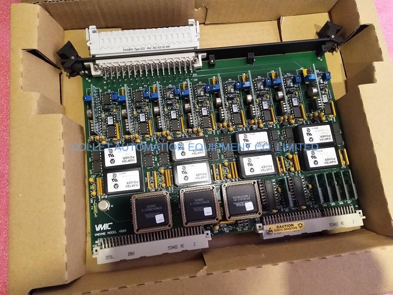
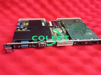
DS200DTBDG1A GE MKV, Terminal Board, Relay/Solenoid
DS200DTBD-Contact Qutput ExpansionTermination Module
The Contact Output Expansion Termination Module (DTBD) is located in <Q1 1><021> and <O51>. DTBD is connected to the 30 relays on the TCRA in locationfive of<Q11>, <Q21> and <Q51>. Sixteen of the 30 outputs on DTBD in locationfour of <Q21> and <Q51> can be configured as solenoids using hardware jumperson DTBD. Two other contact outputs (#47 and #48) can be used for ignition trans-formers ifJ19 and J20 are connected and the factory-installed wire jumpers are re-moved.
DTBD Connectors
JS1 through JS8- Reads the relay signals from the TCRA board in location five.J8- Receives the power for the solenoids from the TCPD board in the <PD> coreJ19-Connects to J20 to carry 125 V de power for contact outputs #47 and #48.Connected in <Q11> and <Q51>, not connected in <Q21>.
J20-Connects to J19 to carry 125 V dc power for contact outputs #47 and #48.
Connected in <Q1l> and <Q5l>, not connected in <Q21>.
The hardware document in Appendix B and the signal flow diagrams in Appendix Dhave more specific information about connectors on this terminal board.
DTBD Hardware Configuration
P1/M1 through P16/M16 - Solenoid enable for contact outputs #31 through #46 re-spectively. Must be both in or both out.Refer to Appendix A for information on the hardware jumper settings for this board.
Frequently Asked Questions:
1.What is the power supply source for the solenoids on the DS200DTBDG1A module?
The power for the solenoids is received from the TCPD board in the <PD> core through the J8 connector.
2.How is the 125 V dc power for contact outputs #47 and #48 supplied on the DTBD module?
The 125 V dc power for contact outputs #47 and #48 is supplied through the J19 and J20 connectors when they are connected.
3.What is the function of the JS1 through JS8 connectors on the DS200DTBDG1A module?
JS1 through JS8 connectors read the relay signals from the TCRA board in location five.
Datasheet Link:
 DS200DTBDG1A GE MKV, Terminal Board, Relay/Solenoid PDF Datasheet