


|
Manufacture |
GE |
|
Model |
DS200QTBAG1A |
| PN No. | DS200QTBAG1A |
|
Catalog |
MKV |
|
Description |
TERM. BOARD (R-S-T)
|
| Origin | USA |
| HS CODE |
85389091 |
| Dimension |
26*10*5 (CM) |
| Weight | 0.5 kg |
Description:
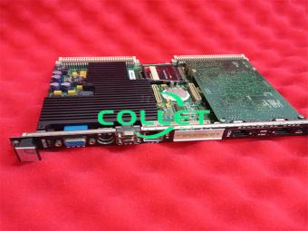
DS200QTBAG1A GE MKV,TERM. BOARD (R-S-T)
DS200QTBA-Termination Module
The Termination Module (QTBA) is located in location six of the <R1>, <R2> and<R3> cores. The QTBA terminal board lands the signals used by the TCOC board in the respective cores. The COREBUS connections are also on the QTBA terminal boards. The inputs for pulse rates and megawatt transducers are connected on the QTBA terminal board and written to the TCOC board. The LVDT/R excitation and servo valve outputs are also connected to the QTBA terminal board from the TCOC board. The Terminal Interface Monitor (TlMN) connections are also located on the QTBA terminal board. A bypass relay that allows the COREBUS to continue to communicate if power is lost on the QTBA terminal board is located on the QTBA terminal board.
Notes As there is no voting being performed for the I/O inputs and outputs, redundant signals would not be used. Signals for the same inputs and outputs would only be used in one of the three locations, <R1>,<R2>, or <R3>.
QTBA Connections
JAI-COREBUS connection. If not used a termination resistor should be installed
JAJ-COREBUS connection, If not used a termination resistor should be installed.
JEE-Communicates the l/0 signals with the respective STCA board for use by the COREBUS.
JGG-Writes the mA input signals, pulse rate input signals and megawatt trans-ducer signals and reads the servo valve output signals to/from the TCOC board inthe respective core.
JFF- Writes the LVDT/R excitation signals and servo output signals to the TCQC board in the respective core.
JRS-Reads the RS232 monitor signals.
The hardware document in Appendix B and the signal flow diagrams in Appendix D have more specific information about connectors on this terminal board.
QTBA Hardware Configuration
J1-Selects the mA input signal currant range, either 0-l mA or 4-20 mA.Refer to Appendix A for information on the hardware jumper settings for this board.
Frequently Asked Questions:
1.What are the termination signals of the DS200QTBAG1A?
The DS200QTBAG1A features various termination signals, such as HP and LP magnetic pickups for measuring speed, flow driver magnetic pickups, water injection flow meters, servo valve outputs, LVDT excitation, and MW transducer signals.
2.Which outputs of the DS200QTBAG1A should not be shorted to ground?
The LVDT excitation outputs of the DS200QTBAG1A must not be shorted to ground.
3.Where is the DS200QTBAG1A installed?
The DS200QTBAG1A is installed on the TBQA. The TBQA board on which the DS200QTBAG1A is mounted has a 9 - pin RS - 232 connector for TIMN diagnostics.
Datasheet Link:
 DS200QTBAG1A GE MKV,TERM. BOARD (R-S-T) PDF Datasheet