


|
Manufacture |
GE |
|
Model |
DS200DTBCG1A |
| PN No. | DS200DTBCG1A |
|
Catalog |
MKV |
|
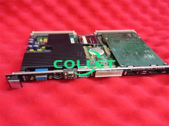
Description |
Terminal Board, Relay/Solenoid
|
| Origin | USA |
| HS CODE |
85389091 |
| Dimension |
26*10*5 (CM) |
| Weight | 0.5 kg |
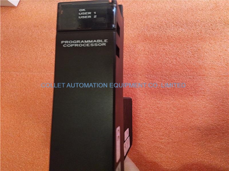
Description:
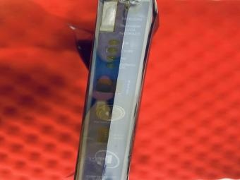
DS200DTBCG1A GE MKV, Terminal Board, Relay/Solenoid
DS200DTBC-Contact Output Termination Module
The Contact Output Termination Module (DTBC) is located in <Q1 1>, <Q21> and<051>. DTBC is connected to the 30 relays on the TCRA in location four of<O21>and <O5l>. Eighteen of the 30 outputs on DTBC in <O5l> can be configured assolenoids using hardware jumpers on DTBC. The DTBC in <O11> is connected tothe four contact output relays on the TCRA in location for of<O11>. The hardware jumpers on the <Q11> DTBC are specially configured for gas manifold blow-offvalve control.
DTBC Connectors
JS1 through JS8 - Reads the relay signals from the TCRA board in location fourJ8- Receives the power for the solenoids from the TCPD board in the <PD> coreJ15-Connects to J16 to carry 125 V dc power for contact outputs #l6, #17, and#18. Not typically used on the <Qll> core.
J16-Connects to Jl5 to carry 125 V dc power for contact outputs #l6, #17, and#18. Can only be connected in the <O5l> core. Not typically used on the <Qll>core.
Frequently Asked Questions:
1. What are the power supply requirements for the DS200DTBCG1A?
The DS200DTBCG1A requires a power supply of 24V DC to 125V DC, with a power consumption of 10W . Specifically, the J15 and J16 connectors supply 125 V DC power to contact outputs 16, 17, and 18 .
2.How many signal wires can be attached to the DS200DTBCG1A board?
220 signal wires can be attached to it.
3.What are the unique connector styles offered in the DS200DTBCG1A assembly?
The unique connector styles include JS1-JS8 TCRA Board Relay Signal Connectors, J8 TCPD Board Solenoid Power Connector, J15 125 V dc Power Connector, and J16 125 V dc Power Connector.
Datasheet Link:
 DS200DTBCG1A GE MKV, Terminal Board, Relay/Solenoid PDF Datasheet