


|
Manufacture |
GE |
|
Model |
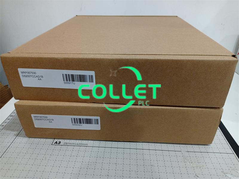
DS200TCCAG1B |
| PN No. | DS200TCCAG1B |
|
Catalog |
Mark V |
|
Description |
Common Analog Card
|
| Origin | USA |
| HS CODE |
85389091 |
| Dimension |
33*10*8 (CM) |
| Weight | 0.5 kg |
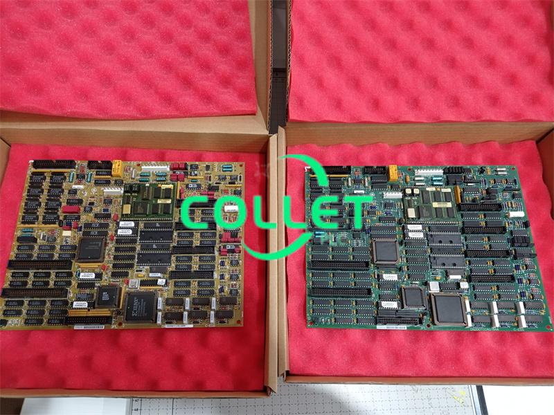
Description:
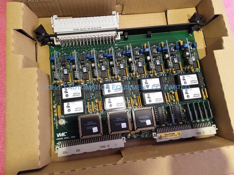
DS200TCCA - Common Analog I/O Board
The Common Analog I/O Board (TCCA), located in the <R5> core, scales and conditions
analog signals from the CTBA, TBQA, and TBCA terminal boards mounted
in the <R5> core. These signals include 4-20 mA inputs and outputs, RTD inputs ,
thermocouple inputs, shaft voltage inputs, and shaft current inputs. The signals are
written to the STCA board via the 3PL connector.
TCCA Connectors
2PL Distributes power from the TCPS board in the <R5> core.
3PL The Data Bus between the STCA, TCCA and TCCB boards in core <R5>. Conditioned signals are carried on 3PL for transferring to the COREBUS.
JAA Carries the 4-20 mA output signals to the CTBA terminal board.
JBB Carries the shaft voltage and current signals and 4-20 mA input signals from the CTBA terminal board.
JCC Carries RTD input signals from the TBCA terminal board.
JDD Carries RTD input signals from the TBCA terminal board.
JAR/S/T Carries Thermocouple input signals and cold junction inputs from the TBQA terminal board.
JC Carries the Power supply diagnostic signals from TCPS.
JEE Typically not used.
The hardware document in Appendix B and the signal flow diagrams in Appendix D
contain more information.
TCCA Configuration
1.Hardware. There are three hardware jumpers - J1, JP2, and JP3 on the TCCA board. J1 is used to enable/disable the serial RS232 port. JP2 is used to disable the oscillator for card test. JP3 is used for factory test. Refer to Appendix A for information on the hardware jumper settings for this board.
2.Software. I/O configuration constants for the thermocouples, RTDs, mA inputs and outputs, and the shaft voltage and current settings are entered in the I/O Configuration Editor located on the HMI as described below.
TCCA 4 - 20 mA Input CircuitThe TCCA board provides the circuitry for the 4-20 mA input signals. The signals are read from the CTBA terminal board via the JBB connector. The transducer current is dropped across a burden resistor and the voltage drop is read by the TCCA board and written to the I/O Engine via the 3PL connector.
TCCA 4-20 mA Output Circuit
The TCCA board provides the circuitry for driving 4-20 mA outputs to the CTBA terminal board via the JAA connector. These signals are typically used to drive remote instrumentation for monitoring.
TCCA RTD Circuit
The circuitry that supplies excitation to the RTDs from the TBCA terminal board is located on the TCCA board. A steady current is sent through the RTD and when the temperature changes, the resistance changes causing the voltage on the RTD to change. The TCCA board measures, scales, and conditions the voltage signal. The RTD signals are read from the TBCA terminal board by the TCCA board over the JCC and JDD connectors. The TCCA board sends the signals to the I/O Engine via the 3PL connector. The type of RTD is selected using I/O configuration constants.
TCCA Thermocouple Circuit
The thermocouple inputs are read by the TBQA terminal board. The cold junction signals are provided by the cold junction circuitry located on the TBQA terminal board. These values are used by the TCCA board to calculate the cold junction compensation. The TCCA board uses the thermocouple input and compensation value to calculate the actual temperature read by the thermocouple. The I/O Engine reads the value via the 3PL connector. Thermocouple types and curves are selected using I/O configuration constants.
TCCA Shaft Monitoring
The monitoring for the turbine shaft voltage and current is provided by the TCCA board. These signals are read from the CTBA terminal board via the JBB connector. The signals are written to the I/O Engine via the 3PL connector.
Frequently Asked Questions:
1.What is the current of the input and output of DS200TCCAG1B?
4-20 mA
2.How does DS200TCCAG1B connect to the corresponding operator interface?
DS200TCCAG1B connects to the operator interface through the CTBA card.
3.When does the warranty period start?
One year from the time the client receives the goods.
Datasheet Link:
 DS200TCCAG1B GE Mark V, Common Analog I/O Board PDF Datasheet


