|
Manufacture |
GE |
|
Model |
DS200TBQDG1ACC |
| PN No. |
DS200TBQDG1ACC |
|
Catalog |
MKV |
|
Description |
TERM BD (R-S-T) EXT |
| Origin | U.S.A. |
| HS CODE |
85389091 |
| Dimension |
38*32*4 (CM) |
| Weight | 0.6 kg |
Description:
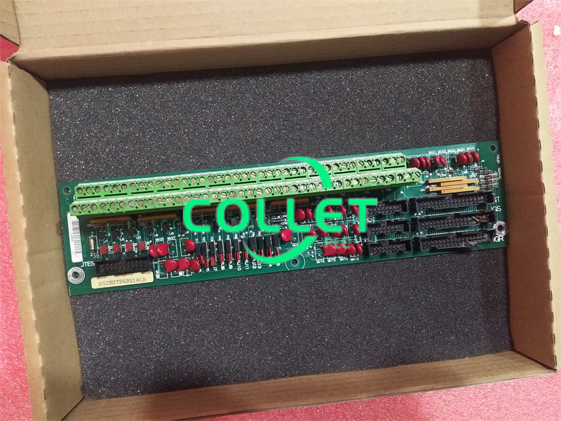
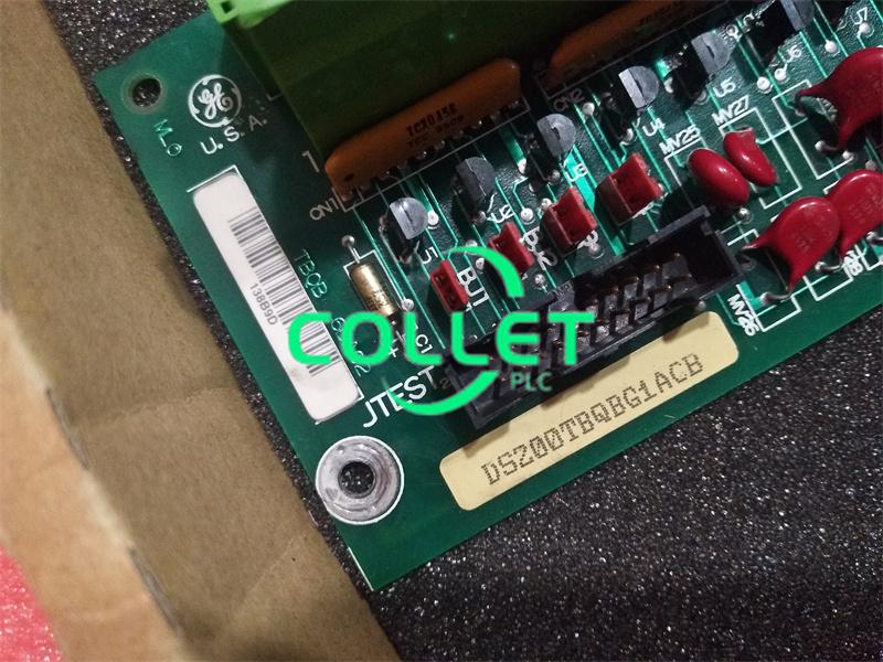
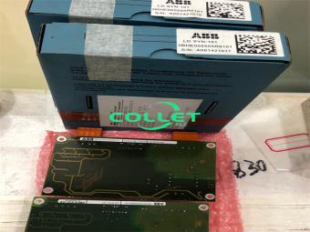
DS200TBQDG1A is an I/O Terminal Circuit Board under Mark V. Two terminal blocks are included on the GE RST Extension Analog Termination Board DS200TBQDG1A. Each block comprises 107 signal wire terminals.
Multiple test points, two jumpers, and three 34-pin connections are also included on the GE RST Extension Analog Termination Board DS200TBQDG1A.
On the board, the jumpers are labeled BJ1 and BJ2. You can utilize the jumpers to configure the board's processing to satisfy the drive's specific requirements when you initially install it. The information provided in the textual material that came with the board can be used by the installer to accomplish this.
On the board, each jumper has three pins. When the jumper covers two pins, one position is specified (for example pins 1 and 2). When two other pins are covered by the jumper, the other position is defined (for example pins 2 and 3).
The installer cannot relocate some jumpers since they only support one jumper position. At the production, the alternate position is utilized to test a specific circuit or function of the board.
The installer must check the new board and the old board together and adjust the jumpers on the new board to the same position as the jumpers on the old board while replacing the board since the original board is defective.
The installer can either take notes on the jumper positions on the problematic board and match them up on the new board. Alternatively, compare the two boards side by side and match the jumpers on the fresh board to the jumpers on the damaged board.
