+8618060982349

259B2460APG1 GE MKVI, Protection Rack (no cards)

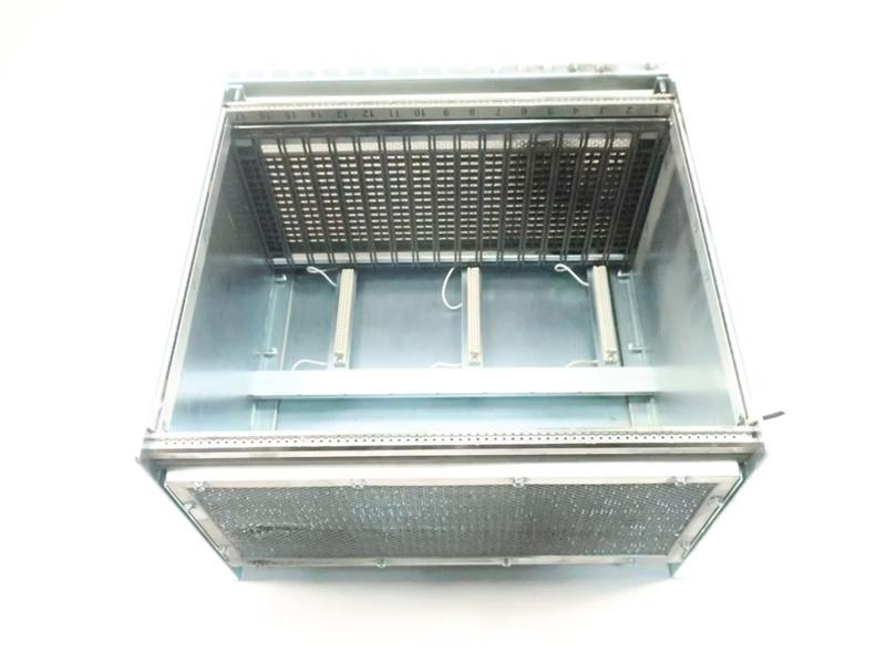
259B2460APG1 is a VPRO Protection Rack and is manufactured by the GE

  • Item NO.:

    259B2460APG1
  • Payment:

    T/T
  • Market Price:

    $11200
  • Product Origin:

    U.S.A.
  • Shipping Port:

    Xiamen
  • Lead Time:

    5-7 days
  • Goods Stock:

    2
  • Product weight:

    10.5 kg


Manufacture
GE
Model
259B2460APG1
PN No. 259B2460APG1
Catalog
MKVI
Description
Protection Rack
Origin U.S.A.
HS CODE 85389091
Dimension 12*6*4 (CM)
Weight 10.5 kg

Description:

This DS200TBQAG1ABB Thermocouple Termination Module was originally manufactured by General Electric for use in their Mark V Turbine Control System Series, as described above. The Mark V Series that this DS200TBQAG1ABB PCB belongs to has specific applications in the control and management systems of compatible wind, steam, and gas turbine automated drive assemblies, and is considered a General Electric legacy series given its original manufacturer's production discontinuation in the years following its initial release. While deemed as a legacy series, the Mark V Turbine Control System Series that this DS200TBQAG1ABB Thermocouple Termination Module belongs to is also considered one of the final General Electric Mark product series to make use of their patented Speedtronic control system technology, a technology first introduced alongside the rollout of the Mark I Series in the late 1960s. This DS200TBQAG1ABB PCB, while definable as a Thermocouple Termination Module in its own right, is not the originally-developed product of this functionality to feature within the Mark V Series; that would be the DS200TBQAG1 Thermocouple Termination Module missing all three of this DS200TBQAG1ABB PCB's three product revisions.

Hardware Tips and Specifications

As with any product featured in General Electric's Mark V Turbine Control System Series, this DS200TBQAG1ABB PCB makes use of its own series of functionality-introducing hardware components and component specifications. The GE RST Terminal Board DS200TBQAG1ABB features 2 90-pin terminal blocks to support a maximum of 180 signal wires. The terminal blocks are labeled TB1 and TB2. The GE RST Terminal Board DS200TBQAG1ABB also contains 3 20-pin connectors. As indicated in this DS200TBQAG1ABB product offering's original instructional manual materials and documentation, this DS200TBQAG1ABB PCB's assembly does not make use of any one manually-moveable hardware jumper or customizable piece of hardware, although several unique connectors are available to its assembly. Some of the connectors established on the base circuit board of this DS200TBQAG1ABB product offering include:

The JAR TCQA and TCCA Boards Thermocouple Signals 1-15 and Cold Junction Signals Connector
The JAS TCQA and TCCA Boards Thermocouple Signals 16-30 and Cold Junction Signals Connector
The JAT TCQA and TCCA Boards Thermocouple Signals 31-45 and Cold Junction Signals Connector
All of the above DS200TBQAG1ABB Thermocouple Termination Module connectors listed have been named through a combination of their factory-printed nomenclature labels, Mark V Series interfacing potentials, and specific signal applications within the Mark V Turbine Control System Series. Both the TCQA and TCCA Boards so important to the functionality of this DS200TBQAG1ABB device's greater Mark V Series automated drive assembly are additionally available for repair or replacement here today.

 When you first install the GE RST Terminal Board DS200TBQAG1ABB the written materials that come with the board describe the signal connections that can be made to the terminals. After you understand which terminal to connect a signal wire to, you must strip the insulation off the end of the signal wire to expose roughly 0.5 inch. Then, loosen the screw and insert  the wire into the terminal. You can next tighten the screw to secure the wire. Pull the wire gently to check that it is installed in the terminal and cannot easily be removed. However, when you replace the board you only must remove the signal wires from the old board and reinstall them in the same terminal in the replacement board. Because you potentially have multiple signal wires to reattach, care must be taken to ensure you attach them to the right terminal. Before you start, check with individuals that are qualified to remove power to the drive. Installers that are familiar with the installation of the drive will understand the power cabling, signal cabling, and ground wiring. An electrician familiar with the installation would also be qualified to remove the power. Some capacitors on the boards in the drive retain power after the power is removed from the drive. However, after 30 seconds the power exits the capacitors and other components and the board is free of current.
Two 90-pin terminal blocks on the GE RST Terminal Board DS200TBQAG1ABB support a maximum of 180 signal lines. TB1 and TB2 are the names of the terminal blocks. Three 20-pin connectors are also included on the GE RST Terminal Board DS200TBQAG1ABB.

The written instructions that come with the GE RST Terminal Board DS200TBQAG1ABB outline the signal connections that can be made to the terminals when you initially install them. After you've figured out which terminal to attach a signal wire to, you'll need to remove the insulation from the signal wire's end to expose around 0.5 inches. The wire should then be inserted into the terminal after loosening the screw. To secure the wire, tighten the screw. Pull the wire gently to make sure it's securely fastened in the terminal and can't be easily withdrawn.
When replacing the board, however, all you have to do is remove the signal wires from the old one and put them in the same terminal on the new one. Because you may have numerous signal wires to reconnect, you must be careful to connect them to the correct terminal. Before you begin, make sure you have somebody who are qualified to turn off the drive's power. Installers who are knowledgeable with the drive's installation will be familiar with the power, signal, and ground wiring. An electrician who is familiar with the setup would be qualified to turn off the electricity.
Some capacitors on the drive's boards maintain power even after the drive is turned off. The power exits the capacitors and other components after 30 seconds, and the board is free of the current.


Datasheet Link:

DS200TBQAG1ABB GE MKV, Thermocouple Terminal Board Datasheet General Electric

一年保修插画-一年保修手绘-一年保修卡通图-摄图新视界


Leave A Message
If you are interested in our products and want to know more details,please leave a message here,we will reply you as soon as we can.
Related Products
GE IC697CHS750 Module
GE IC697CHS750 Module/ New /in Stock/Online sale

GE IC697CHS750 Module

be in great demand

View More
GE IC697CMM742 Module
GE IC697CMM742 Module/ New /in Stock/Online sale

GE IC697CMM742 Module

Best selling

View More
GE IC697CPU731 Module
GE IC697CPU731 Module/ New /in Stock/Online sale

GE IC697CPU731 Module

Rare is precious


View More
GE IC697CPX772 Module
GE IC697CPX772 Module/ New /in Stock/Online sale

GE IC697CPU731Module

As long as you need it, we have it

View More
GE IS200DSPXH1C Module
GE IS200DSPXH1C DRIVE DSP CARD / New in Stock

GE IS200DSPXH1C

New original spot, price concessions, welcome to consult.


View More
GE IC697MDL753 Module
GE IC697MDL753 Module/ New /in Stock/Online sale

GE IC697MDL753 Module


As long as you need it, we have it


View More
GE IC697BEM731 Module
GE IC697BEM731 Module/ New /in Stock/Online sale

GE IC697BEM731 Module

be in great demand

View More
GE IC697PWR711 Module
GE IC697PWR711 Module/ New /in Stock/Online sale


GE IC697PWR711 Module

New original spot, price concessions, welcome to consult.


View More

click here to leave a message

Leave A Message
If you are interested in our products and want to know more details,please leave a message here,we will reply you as soon as we can.

Home

Products

about

contact